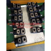
叶片泵:分为双作用叶片泵和单作用叶片泵。这种泵流量均匀、运转平稳、噪音小、作压力和容积效率比齿轮泵高、结构比齿轮泵复杂。
20V2A 叶片泵
20V2A-1A22R
20V2A-1B22R
20V2A-1C22R
20V2A-1D22R
20V3A
20V3A-1A22R
20V3A-1B22R
20V3A-1C22R
20V3A-1D22R
20V4A
20V4A-1A22R
20V4A-1B22R
20V4A-1C22R
20V4A-1D22R
20V5A
20V5A-1A22R
20V5A-1B22R
20V5A-1C22R
20V5A-1D22R
20V6A
20V6A-1A22R
20V6A-1B22R
20V6A-1C22R
20V6A-1D22R
20V7A
20V7A-1A22R
20V7A-1B22R
20V7A-1C22R
20V7A-1D22R
20V8A
20V8A-1A22R
20V8A-1B22R
20V8A-1C22R
20V8A-1D22R
20V9A
20V9A-1A22R
20V9A-1B22R
20V9A-1C22R
20V9A-1D22R
20V10A
20V10A-1A22R
20V10A-1B22R
20V10A-1C22R
20V10A-1D22R
20V11A
20V11A-1A22R
20V11A-1B22R
20V11A-1C22R
20V11A-1D22R
20V12A
20V12A-1A22R
20V12A-1B22R
20V12A-1C22R
20V12A-1D22R
20V14A
20V14A-1A22R
20V14A-1B22R
20V14A-1C22R
20V14A-1D22R
25V10A
25V10A-1A22R
25V10A-1B22R
25V10A-1C22R
25V10A-1D22R
25V12A
25V12A-1A22R
25V12A-1B22R
25V12A-1C22R
③蓄能器参数的确定与验算。 篇a. 蓄能器压力的确定:对低压回路,选气囊式蓄能器,按绝热状态考虑,最低压力p1=p+ E Apmax = 5MPa,最高压力P2=(1.1~1.25)p1=1. 25x5=6. 25MPa,充气压力Po=(0. 7~0.9)p1=0.8x5=4MPa;对高压回路,最低压力P1= 13MPa,最高压力P2=1. 1x13= 14.3MPa,充气压力Po =0.8x13= 10. 4MPa。
(3) determination and checking calculation of accumulator parameters. Article a. Determination of accumulator pressure: for low voltage circuit, air bag accumulator, according to the insulation state, the minimum pressure p _ 1 ≤ p + E Apmax = 5 MPA, the maximum pressure P _ 2 = (1.1 ≤ 1. 25) p _ 1 ≤ 1. 25x5 / 6. 25MPA, inflatable pressure Po= (0. 5%). For high pressure circuits, the minimum pressure P _ 1 = 13 MPA, the highest pressure P _ 2 ≤ 1. 1x13 = 14.3MPA, inflatable pressure Po = 0.8x13 = 10. 4MPa .
b.蓄能器容量的确定:对低压回路,从流量时间循环图中可知,尖峰流量在移动缸工作期间,为满足移动缸要求,最大负载时泵工作时间t=3.5s,缸耗油量4x5.53=22.12L,漏损系数1.2,则蓄能器工作容积VB1=22.12x1.2-3. 5x( 100+ 168)/60= 10.9IL,蓄能器总容积Von=Vp2/{40 7143x[(15)0.7143-( 1/6.25)0.7143]}= 10. 91/0.1256=86.9L,选择标准皮蓄能器3x40=120L;对高压回路,从流量时间循环图中可知,尖峰流量在脱模缸工作期间,为满足脱模缸要求,最大负载时泵工作时间t=0s,缸耗油量2x1.9=3.8L,漏损系数1.2,则蓄能器工作容积Vp2=3. 8x1.2=4.56L,蓄能器工作总容积Vo2= Vp2/10.40.7143x[(1/13)0.7143-(1/14.3)0.743]}=4.56/0.0561=81.3L,选择标准皮蓄能器3x40= 120L。
b. Determination of accumulator capacity: for the low voltage loop, it can be seen from the flow time cycle diagram that the peak flow rate is in order to meet the requirements of the moving cylinder during the working period of the moving cylinder. At the maximum load, the working time of the pump is t ≤ 3.5s, the fuel consumption of the cylinder is 4x5.53 ≤ 22.12L, and the leakage coefficient is 1.2, then the working volume of the accumulator is VB1=22.12x1.2-3.. 5x (100 + 168) / 60 = 10.9IL, total volume of accumulator Von=Vp2/ {407143x [(15) 0.7143-(1 ≤ 6.25) 0.7143]} = 10. 91 ≤ 0.1256 × 86.9L, and the standard skin accumulator 3x40 ≤ 120L was selected. For the high voltage loop, it can be seen from the flow time cycle diagram that the peak flow rate is in order to meet the requirements of the release cylinder during the working period of the release cylinder. At the maximum load, the working time of the pump is t ≤ 0s, the fuel consumption of the cylinder is 2x1.9 ≤ 3.8L, and the leakage coefficient is 1.2, then the working volume of the accumulator Vp2=3. 8x1.2 ≤ 4.56L, the total working volume of accumulator Vo2= Vp2/10.40.7143x [(1 ≤ 13) 0.7143-(1 ≤ 14.3) 0.743]} = 4.56 ≤ 0.0561 ≤ 81.3 L, and the standard skin accumulator 3x40 = 120L was selected.


